Apply Shoulder Rollover Lock
Use this dialog box to create a control line for shoulder points using high and low-side algebraic differences. This command creates a control line using the input values; then, assigns the control line to the specified point.
Shoulder Point -specifies the shoulder point that is controlled by rollover. Select the point from the list or use the locate button to identify the point.
Control Line Name -specifies a name for the control line.
High Side
- Difference -specifies the absolute difference between the shoulder slope and the road slope. This value is always positive.
- Maximum Slope -indicates, when checked on, that an absolute upper bound on the shoulder slope is used. Specify this value, including the correct negative or positive sign, in the field.
- Instantaneous Shoulder Rollup Transition Option - applies only when the specified high side difference is less than the current difference between the shoulder and the edge of pavement. For example, if normal crown on the road is 2%, and the shoulder is at 4%, the difference is 2%. Any high side difference less than 2% will require an instantaneous change when rotation of the high side pavement commences to satisfy the high side difference requirement.
- Specified Length - determines the length of the transition of the shoulder super before the pavement starts to super. Specify a value greater than 0.
- Match Transition Slope -when checked, the length of the shoulder rollup transition is calculated such that the slope of the shoulder transition super control line matches the slope of the edge of pavement control line.
- Low Side - Difference specifies the absolute difference between the shoulder slope and the road slope. This value is always positive.
- Minimum Slope -indicates, when checked on, that an absolute lower bound on the shoulder slope is used. Specify this value, including the correct negative or positive sign, in the field.
Limits
- Station -specifies, when checked on, that station range limits are used.
- Start -identifies the start station. Type in this value or identify the station using the locate button.
- Stop -identifies the stop station. Type in this value or identify the station using the locate button.
- Apply -applies the values, creates the control lines and assigns the point control.
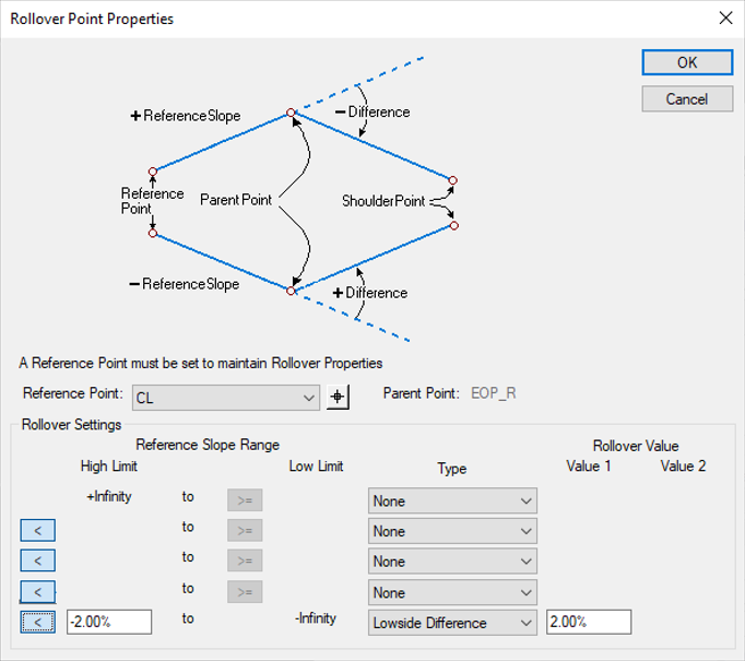
Rollover Lock Settings
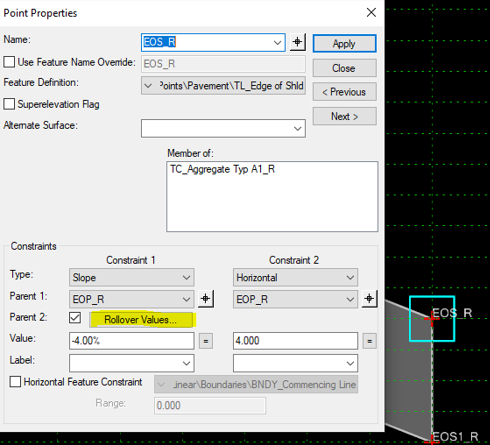
The Rollover Lock would be created on the point(s) EOS_R and EOS_L.
To create the rollover lock edit point EOS_R or EOS_L, turn on Parent 2 check box and click the Rollover Values… button.
Example 1
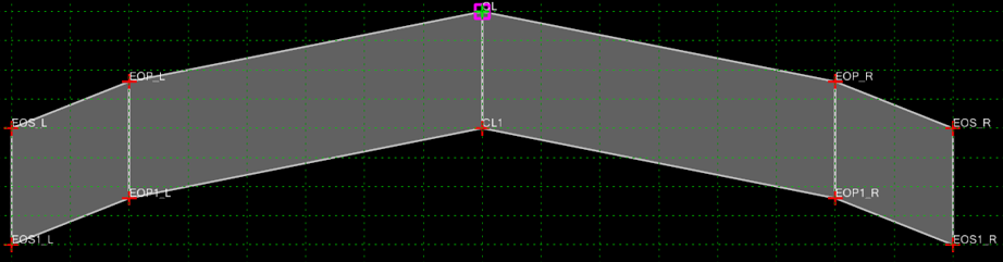
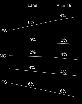
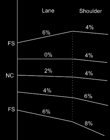
We will start with a case for a rollover. We will only look at the right side of the template shown on the previous page. In this case we want the rollover for the shoulder to be as follows.
- When at normal crown the shoulder (EOP_R to EOS_R) has a slope of -2% difference from the lane.
- As the template transitions into a left-hand curve the -2% difference is maintained to full superelevation
- As the template transitions into a right-hand curve the shoulder stays at -4% until the lane gets to -4%.
- When the lane gets to -4% the shoulder matches the slope of the lane to full superelevation.
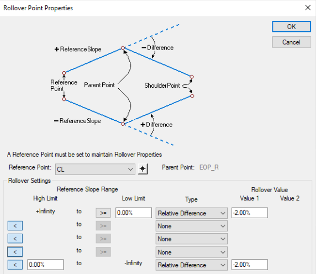
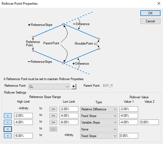
The below entries would be applied to the rollover locks on the EOS_R.

Notice the following:
- From a positive infinite lane slope to a -2% lane slope there is a relative difference of -2% between the lane and shoulder.
- From a -2% lane slope to a -4% lane slope the shoulder maintains a slope of -4%.
- From a -4% lane slope to a negative infinite lane slope there is a relative difference of 0% between the lane and shoulder.
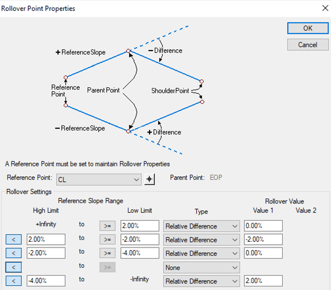
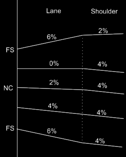
Example 2
Now let's make a change to the rollover locks so that when the lane slope is between -4% and -6% the shoulder slope changes from a -4% gradually to a 0% slope between. After a -6% the shoulder maintains a 0% slope.

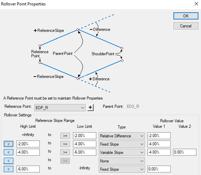
Example 3
Then next example uses the Highside Difference option. This means that when the lane has a positive slope the shoulder slope will be held at a -4% difference. When the lane has a negative slope, the shoulder will always be at -4%.

Example 4

The following rollover setting will be for EOS_R and OEOS_R respectively.